Airfoils
and Lift
An
airfoil is a device which gets a useful reaction from
air moving over its surface. When an airfoil is moved
through the air, it is capable of producing lift.
Wings, horizontal tail surfaces, vertical tails surfaces,
and propellers are all examples of airfoils.
Generally
the wing of small aircraft will look like the cross-section
of the figure above. The forward part of an airfoil
is rounded and is called the leading edge. The aft
part is narrow and tapered and is called the trailing
edge. A reference line often used in discussing airfoils
is the chord, an imaginary straight line joining the
extremities of the leading and trailing edges.
Angle
of Incidence: The angle of incidence is the angle
formed by the longitudinal axis of the airplane and
the chord of the wing. The longitudinal axis is an
imaginary line that extends lengthwise through the
fuselage from nose to tail. The angle of incidence
is measured by the angle at which the wing is attached
to the fuselage. The angle of incidence is fixed.
It normally cannot be changed by the pilot.
Bernoulli's
Principle: To understand how lift is produced,
we must examine a phenomenon discovered many years
ago by the scientist Bernoulli and later called Bernoulli's
Principle: The pressure of a fluid (liquid or gas)
decreases at points where the speed of the fluid increases.
In other words, Bernoulli found that within the same
fluid, in this case air, high speed flow is associated
with low pressure, and low speed flow with high pressure.
This principle was first used to explain changes in
the pressure of fluid flowing within a pipe whose
cross-sectional area varied. In the wide section of
the gradually narrowing pipe, the fluid moves at low
speed, producing high pressure. As the pipe narrows
it must contain the same amount of fluid. In this
narrow section, the fluid moves at high speed, producing
low pressure.
An
important application of this phenomenon is made in
giving lift to the wing of an airplane, an airfoil.
The airfoil is designed to increase the velocity of
the airflow above its surface, thereby decreasing
pressure above the airfoil. Simultaneously, the impact
of the air on the lower surface of the airfoil increases
the pressure below. This combination of pressure decrease
above and increase below produces lift.
Lift:
Probably you have held your flattened hand out of
the window of a moving automobile. As you inclined
your hand to the wind, the force of air pushed against
it forcing your hand to rise. The airfoil (in this
case, your hand) was deflecting the wind which, in
turn, created an equal and opposite dynamic pressure
on the lower surface of the airfoil, forcing it up
and back. The upward component of this force is lift;
the backward component is drag .
Pressure
is reduced is due to the smaller space the air has
above the wing than below. Air cannot go through the
wing, so it must push around it. The surface air molecules
push between the wing and outer layers of air. Due
to the bump of the airfoil, the space is smaller and
the molecules must go faster. According to Bernoulli's
Law, faster air has lower air pressure, and thus the
high pressure beneath the wing pushes up to cause
lift.
Forces
Acting on an Airplane
The
airplane in straight-and-level unaccelerated flight
is acted on by four forces. The four forces are lift,
gravity, thrust and drag.
The
airplane in straight-and-level unaccelerated flight
is acted on by four forces--lift, the upward acting
force; weight, or gravity, the downward acting force;
thrust, the forward acting force; and drag, the backward
acting, or retarding force of wind resistance.
Lift
opposes gravity. Thrust opposes drag.
Drag
and weight are forces inherent in anything lifted
from the earth and moved through the air. Thrust and
lift are artificially created forces used to overcome
the forces of nature and enable an airplane to fly.
The engine and propeller combination is designed to
produce thrust to overcome drag. The wing is designed
to produce lift to overcome the weight (or gravity).
In
straight-and-level, unaccelerated flight, (Straight-and-level
flight is coordinated flight at a constant altitude
and heading) lift equals weight and thrust equals
drag, though lift and weight will not equal thrust
and drag. Any inequality between lift and weight will
result in the airplane entering a climb or descent.
Any inequality between thrust and drag while maintaining
straight-and-level flight will result in acceleration
or deceleration until the two forces become balanced.
Axes
of Rotation
An airplane may turn about three axes. Whenever the
attitude of the airplane changes in flight (with respect
to the ground or other fixed object), it will rotate
about one or more of these axes. Think of these axes
as imaginary axles around which the airplane turns
like a wheel. The three axes intersect at the center
of gravity and each one is perpendicular to the other
two.
Longitudinal
Axis: The imaginary line that extends lengthwise
through the fuselage, from nose to tail, is the longitudinal
axis. Motion about the longitudinal axis is roll and
is produced by movement of the ailerons located at
the trailing edges of the wings.
Lateral
Axis: The imaginary line which extends crosswise,
wing tip to wing tip, is the lateral axis. Motion
about the lateral axis is pitch and is produced by
movement of the elevators at the rear of the horizontal
tail assembly.
Vertical
Axis: The imaginary line which passes vertically
through the center of gravity is the vertical axis.
Motion about the vertical axis is yaw and is produced
by movement of the rudder located at the rear of the
vertical tail assembly.
Flight
Control Surfaces
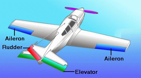
The three primary flight controls are the ailerons,
elevator and rudder.
Ailerons:
The two ailerons, one at the outer trailing edge of
each wing, are movable surfaces that control movement
about the longitudinal axis. The movement is roll.
Lowering the aileron on one wing raises the aileron
on the other. The wing with the lowered aileron goes
up because of its increased lift, and the wing with
the raised aileron goes down because of its decreased
lift. Thus, the effect of moving either aileron is
aided by the simultaneous and opposite movement of
the aileron on the other wing. Rods or cables connect
the ailerons to each other and to the control wheel
(or stick) in the cockpit. When pressure is applied
to the right on the control wheel, the left aileron
goes down and the right aileron goes up, rolling the
airplane to the right. This happens because the down
movement of the left aileron increases the wing camber
(curvature) and thus increases the angle of attack.
The right aileron moves upward and decreases the camber,
resulting in a decreased angle of attack. Thus, decreased
lift on the right wing and increased lift on the left
wing cause a roll and bank to the right.
Elevators:
The elevators control the movement of the airplane
about its lateral axis. This motion is pitch. The
elevators form the rear part of the horizontal tail
assembly and are free to swing up and down. They are
hinged to a fixed surface--the horizontal stabilizer.
Together, the horizontal stabilizer and the elevators
form a single airfoil. A change in position of the
elevators modifies the camber of the airfoil, which
increases or decreases lift.
Like the ailerons, the elevators are connected to
the control wheel (or stick) by control cables. When
forward pressure is applied on the wheel, the elevators
move downward. This increases the lift produced by
the horizontal tail surfaces. The increased lift forces
the tail upward, causing the nose to drop. Conversely,
when back pressure is applied on the wheel, the elevators
move upward, decreasing the lift produced by the horizontal
tail surfaces, or maybe even producing a downward
force. The tail is forced downward and the nose up.
The elevators control the angle of attack of the wings.
When back pressure is applied on the control wheel,
the tail lowers and the nose raises, increasing the
angle of attack. Conversely, when forward pressure
is applied, the tail raises and the nose lowers, decreasing
the angle of attack.
Rudder:
The rudder controls movement of the airplane about
its vertical axis. This motion is yaw. Like the other
primary control surfaces, the rudder is a movable
surface hinged to a fixed surface which, in this case,
is the vertical stabilizer, or fin. Its action is
very much like that of the elevators, except that
it swings in a different plane--from side to side
instead of up and down. Control cables connect the
rudder to the rudder pedals.
Trim
Tabs: A trim tab is a small, adjustable hinged
surface on the trailing edge of the aileron, rudder,
or elevator control surfaces. Trim tabs are labor
saving devices that enable the pilot to release manual
pressure on the primary controls.
Some airplanes have trim tabs on all three control
surfaces that are adjustable from the cockpit; others
have them only on the elevator and rudder; and some
have them only on the elevator. Some trim tabs are
the ground-adjustable type only.
The tab is moved in the direction opposite that of
the primary control surface, to relieve pressure on
the control wheel or rudder control. For example,
consider the situation in which we wish to adjust
the elevator trim for level flight. ("Level flight"
is the attitude of the airplane that will maintain
a constant altitude.) Assume that back pressure is
required on the control wheel to maintain level flight
and that we wish to adjust the elevator trim tab to
relieve this pressure. Since we are holding back pressure,
the elevator will be in the "up" position.
The trim tab must then be adjusted downward so that
the airflow striking the tab will hold the elevators
in the desired position. Conversely, if forward pressure
is being held, the elevators will be in the down position,
so the tab must be moved upward to relieve this pressure.
In this example, we are talking about the tab itself
and not the cockpit control.
Rudder and aileron trim tabs operate on the same principle
as the elevator trim tab to relieve pressure on the
rudder pedals and sideward pressure on the control
wheel, respectively.
Elevon:
Delta winged aircraft can not use conventional 3 axis
flight control systems because of their unique delta
shape. Therefore, it uses a device called an elevon.
It is a combination of ailerons and elevators.
The elevon is used as an aileron. Ailerons control
motion along the longitudinal axis. The longitudinal
axis is an imaginary line that runs from the nose
to the tail. Motion about the longitudinal axis is
called roll.
The elevon is also used as an elevator. Elevators
control motion along the lateral axis. The lateral
axis is an imaginary line that extends crosswise,
from wingtip to wingtip. Motion about the lateral
axis is called pitch.
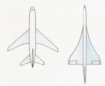
Delta
winged aircraft use elevons as primary flight controls
for roll and pitch.
Laminar
Flow Airfoil
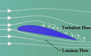
Laminar
Flow is the smooth, uninterrupted flow of air over
the contour of the wings, fuselage, or other parts
of an aircraft in flight. Laminar flow is most often
found at the front of a streamlined body and is an
important factor in flight. If the smooth flow of
air is interrupted over a wing section, turbulence
is created which results in a loss of lift and a high
degree of drag. An airfoil designed for minimum drag
and uninterrupted flow of the boundary layer is called
a laminar airfoil.
The
Laminar flow theory dealt with the development of
a symmetrical airfoil section which had the same curvature
on both the upper and lower surface. The design was
relatively thin at the leading edge and progressively
widened to a point of greatest thickness as far aft
as possible. The theory in using an airfoil of this
design was to maintain the adhesion of the boundary
layers of airflow which are present in flight as far
aft of the leading edge as possible. on normal airfoils
the boundary layer would be interrupted at high speeds
and the resultant break would cause a turbulent flow
over the remainder of the foil. This turbulence would
be realized as drag up the point of maximum speed
at which time the control surfaces and aircraft flying
characteristics would be affected. The formation of
the boundary layer is a process of layers of air formed
one next to the other, ie; the term laminar is derived
from the lamination principle involved.
The
flow next to any surface forms a "boundary layer",
as the flow has zero velocity right at the surface
and some distance out from the surface it flows at
the same velocity as the local "outside" flow. If this boundary layer flows in parllel layers,
with no energy transfer between layers, it is laminar.
If there is energy transfer, it is turbulent.
All
boundary layers start off as laminar. Many influences
can act to destabilize a laminar boundary layer, causing
it to transition to turbulent. Adverse pressure gradients,
surface roughness, heat and acoustic energy all examples
of destabilizing influences. Once the boundary layer
transitions, the skin friction goes up. This is the
primary result of a turbulent boundary layer. The
old "lift loss" myth is just that - a myth.
A favorable
pressure gradient is required to maintain laminar
flow. Laminar flow airfoils are designed to have long
favorable pressure gradients. All airfoils must have
adverse pressure gradients on their aft end. The usual
definition of a laminar flow airfoil is that the favorable
pressure gradient ends somewhere between 30 and 75%
of chord.
Now
Consider the finish on your car in non-rainy conditions.
Dust and leaves have settled on the hood's paint.
We go for a drive. At once the leaves blow off. But
the dust remains. We speed up. Even if we go very
fast, the dust remains because of the thin layer of
air that moves with the car. If you drive with dew
on your car, the dew will not so quickly be blown
dry where the air flow has this thin laminar layer.
Downstream, where the laminar flow has become turbulent,
the air flow quickly dries the dew.
In
the fifties this was dramatically shown in a photograph
of the top of a sailplane wing (inflight) that had
dew on it. A few tiny seeds had landed on forward
area the wing while on the ground. In flight these
seeds, tiny though they were, reached through the
laminar layer and caused micro-turbulence causing
the dew to be blown dried in an expanding vee shaped
area down stream of each tiny seed.
Profile drag
This comprises two
components: surface friction drag and normal pressure
drag (form drag).
Surface friction drag
This arises from the
tangential stresses due to the viscosity or "stickiness" of the air. When air flows over any part of an aircraft
there exists, immediately adjacent to the surface,
a thin layer of air called the boundary layer, within
which the air slows from its high velocity at the
edge of the layer to a standstill at the surface itself.
Surface friction drag depends upon the rate of change
of velocity through the boundary layer, i.e. the velocity
gradient. There are two types of boundary layer, laminar
and turbulent, the essential features of which are
shown in Fig 8. Although all combat aircraft surfaces
develop a laminar boundary layer to start with, this
rapidly becomes turbulent within a few per cent of
the length of the surface. This leaves most of the
aircraft immersed in a turbulent boundary layer, the
thickness of which increases with length along the
surface. The velocity and hence pressure variations
along the length of any surface can have adverse effects
on the behavior of the boundary layer, as will be
discussed later.
Surface friction drag
can amount to more than 30% of the total drag under
cruise conditions.
Normal pressure drag
(form drag)
This also depends upon
the viscosity of the air and is related to flow separation.
It is best explained by considering a typical pressure
distribution over a wing section, as shown in Fig
4, first at low AOA and then at high AOA.
At
low AOA the high pressures near the leading edge produce
a component of force in the rearward (i.e. drag) direction,
while the low pressures ahead of the maximum thickness
point tend to suck the wing section forward, giving
a thrust effect. The low pressures aft of the maximum
thickness point tend to suck the wing rearwards, since
they act on rearward-facing surfaces. Without the
influence of the boundary layer, the normal pressure
forces due to the above drag and thrust components
would exactly cancel.
There
is a favorable pressure gradient up to the minimum
pressure point, with the pressure falling in the direction
of flow. This helps to stabilize the boundary layer.
Downstream of the minimum pressure point, however,
the thickening boundary layer has to flow against
an adverse pressure gradient. Viscous effects reduce
momentum within the boundary layer, and the thickness
of the layer further increases so that the external
flow "sees" a body which does not appear
to close to a point at the trailing edge. A narrow
wake is formed as the boundary layer streams off the
section. This prevents the pressures on the aft-facing
surface of the wing section from recovering to the
high value obtaining near the stagnation point on
the leading edge, as they would have done if a boundary
layer had not formed. There is thus a lower than expected
pressure acting on the aftfacing surface, giving rise
to normal pressure drag. In the low-AOA case this
component is small, most of the profile drag being
made up of surface friction drag.
As
the AOA of the wing section is increased, the point
of minimum pressure moves towards the leading edge,
with increasingly high suction being achieved. This
means that the pressure then has to rise by a greater
extent downstream of the minimum pressure point and
that the length of wing surface exposed to the rising
pressure is increased. The resulting adverse pressure
gradient becomes more severe as AOA is increased.
This has serious implications for the boundary layer,
which is always likely to separate from the wing surface
under such conditions.
The Swept Wing
The
whole idea of sweeping an aircraft's wing is to delay
the drag rise caused by the formation of shock waves.
The swept-wing concept had been appreciated by German
aerodynamicists since the mid-1930s, and by 1942 a
considerable amount of research had gone into it.
However, in the United States and Great Britain, the
concept of the swept wing remained virtually unknown
until the end of the war. Due to the early research
in this area, this allowed Germany to successfully
introduce the swept wing in the jet fighter Messerschmitt
ME-262 as early as 1941.
Early
British and American jet aircraft were therefore of
conventional straight-wing design, with a high-speed
performance that was consequently limited. Such aircraft
included the UKGloster Meteor F.4 , the U.S. Lockheed
F-80 Sooting Star and the experimental U.S. jet, the
Bell XP-59A Airacomet.
After
the war German advanced aeronautical research data
became available to the United States Army Air Force
(USAAF) as well as Great Britain. This technology
was then incorporated into their aircraft designs.
Some early jets that took advantage of this technology
were the North American F-86 Sabre, the Hawker Hunter
F.4 and the Supermarine Swift FR.5.
Not
to be outdone, the Soviet Union introduced the swept
wing in the Mikoyan Mig-15 in 1947. This aircraft
was the great rival of the North American F-86 Sabre
during the Korean War.