Reciprocating
Engines
The Four Stroke Engine
1.
The Intake or Admission Stroke
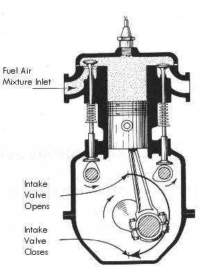
During
the intake or admission stroke, the piston moves downward
as a charge of combustible fuel and air is admitted
into the cylinder through the open intake valve. At
the completion of this stroke the intake valve closes.
2.
The Compression Stroke
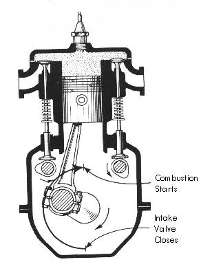
During
the compression stroke, the crankshaft continues to
rotate, the piston is forced upward in the cylinder,
and both intake and exhaust valves are closed. The
movement of the piston upward compresses the fuel-air
mixture.
3.
Power or Expansion Stroke
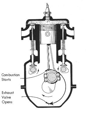
As
the piston approaches the top of its stroke within
the cylinder, an electric spark jumps across the points
of the spark plugs and ignites the compressed fuel-air
mixture. This is the ignition event, or event No.
3. The intake and exhaust valves are closed.
Having
been ignited, the fuel-air mixture burns. It expands
as it burns and drives the piston downward. This causes
the crankshaft to revolve. Since it is the only stroke
and event that furnishes power to the crankshaft,
it is usually called the power stroke, although it
is sometimes called the expansion stroke for purposes
of instruction. This is event No. 4. The intake and
exhaust valves are closed.
4.
The Exhaust or Scavenging Stroke
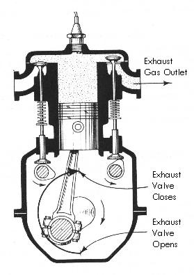
During
the power or expansion stroke, the hot gases obtained
by combustion exert tremendous pressure on the piston
to force it to move downward, but near the end of
the stroke this pressure is greatly reduced because
of the expansion of the gases. At this stage, the
exhaust valve opens as the crankshaft continues to
revolve and the piston is again moved upward in the
cylinder by the connecting rod. The burning gases
remaining in the cylinder are forced out through the
exhaust valve, hence this stroke is usually called
the exhaust stroke, although it may be called the
scavenging stroke for purposes of instruction.
This
completes one engine cycle.
Jet
Engines
Centuries
ago in 100 A.D., Hero, a Greek philosopher and mathematician,
demonstrated jet power in a machine called an "aeolipile."
A heated, water filled steel ball with nozzles spun
as steam escaped. Why? The principle behind this phenomenon
was not fully understood until 1690 A.D. when Sir
Isaac Newton in England formulated the principle of
Hero's jet propulsion "aeolipile" in scientific
terms. His Third Law of Motion stated: "Every
action produces a reaction ... equal in force and
opposite in direction."
The
jet engine of today operates according to this same
basic principle. Jet engines contain three common
components: the compressor, the combustor, and the
turbine. To this basic engine, other components may
be added, including:
1.
A nozzle to recover and
direct the gas energy and possibly divert the thrust
for vertical takeoff and landing as well as changing
direction of aircraft flight.
2.
An afterburneror augmentor,
a long "tailpipe" behind the turbine into
which additional fuel is sprayed and burned to provide
additional thrust.
3.
A thrust reverser, which
blocks the gas rushing toward the rear of the engine,
thus forcing the gases forward to provide additional
braking of aircraft.
4.
A fan in front of the
compressor to increase thrust and reduce fuel consumption.
5.
An additional turbine that can be utilized to drive a propeller or helicopter
rotor.
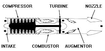
The Turbojet
Engine
The
turbojet is the basic engine of the jet age. Air is
drawn into the engine through the front intake. The
compressor squeezes the air to many times normal atmospheric
pressure and forces it into the combustor. Here, fuel
is sprayed into the compressed air, is ignited and
burned continuously like a blowtorch. The burning
gases expand rapidly rearward and pass through the
turbine. The turbine extracts energy from the expanding
gases to drive the compressor, which intakes more
air. After leaving the turbine, the hot gases exit
at the rear of the engine, giving the aircraft its
forward push ... action, reaction !
For
additional thrust or power, an afterburner or augmentor
can be added. Additional fuel is introduced into the
hot exhaust and burned with a resultant increase of
up to 50 percent in engine thrust by way of higher velocity and more push.
The Turbofan Engine
A
high bypass turbofan engine
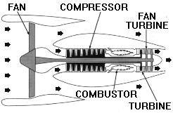
A turbofan
engine is basically a turbojet to which a fan has
been added. Large fans can be placed at either the
front or rear of the engine to create high bypass
ratios for subsonic flight. In the case of a front
fan, the fan is driven by a second turbine, located
behind the primary turbine that drives the main compressor.
The fan causes more air to flow around (bypass) the
engine. This produces greater thrust and reduces specific
fuel consumption.
A low bypass turbofan engine
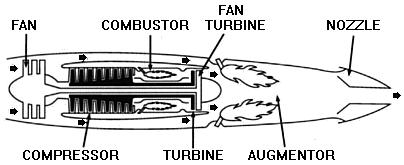
For
supersonic flight, a low bypass fan is utilized, and
an augmentor is added for additional thrust.
The
Turboprop/Turboshaft Engine
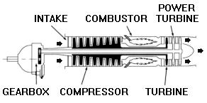
A turboprop engine uses thrust to turn a propeller. As in a turbojet,
hot gases flowing through the engine rotate a turbine
wheel that drives the compressor. The gases then pass
through another turbine, called a power turbine. This
power turbine is coupled to the shaft, which drives
the propeller through gear connections.
A turboshaft is similar to a turboprop engine, differing primarily
in the function of the turbine shaft. Instead of driving
a propeller, the turbine shaft is connected to a transmission
system that drives helicopter rotor blades; electrical
generators, compressors and pumps; and marine propulsion
drives for naval vessels, cargo ships, high speed
passenger ships, hydrofoils and other vessels.
The
Ultra High Bypass Engine
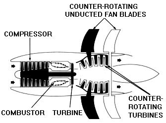
A logical
approach to improving fuel consumption is even higher
bypass technology. Mechanical arrangements can vary.
During the 1980s, GE developed the Unducted Fan UDF®
engine which eliminated the need for a gearbox to
drive a large fan. The jet exhaust drives two counter-rotating
turbines that are directly coupled to the fan blades.
These large span fan blades, made of composite materials,
have variable pitch to provide the proper blade angle
of attack to meet varying aircraft speed and power
requirements. Powerplants such as the UDF® engine
are capable of reducing specific fuel consumption
another 20-30 percent below current subsonic turbofans.